Software segregation is a general architecture/design concept to ensure a failure in one architecture element doesn’t negatively impact or lead to failure in another element. This is to prevent undesirable condition such as mission failure, user harm, financial loss, security breach, usability, performance, etc.
This post is not to provide an academic overview of software architecture, but rather directly focused on medical software, i.e., IEC 62304 standard.
While there are numerous ways to go about segregating risk in an architectural fashion, I put forth a stripped down method which I believe is to be the most straight forward and practical for the general audience.
Software risk segregation is by nature a software architecture activity; you simply cannot conduct proper software risk segregation without having a properly documented architecture.
Terminology
I want to touch on key terminologies defined in IEC 62304 as I’ve seen much misinformation and confusion.
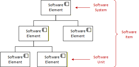
All software elements are referred to as “software item”. The top-most software item is called “software system” and the lower-most software item is called “software unit”. This is important to understand as IEC 62304 defines requirements based on these terms. For example, if a requirement is on the “software item”, then that requirement applies to all software elements.
Similar terminologies are used in other domains such as Computer Software Configuration Item (CSCI), Computer Software Component (CSC), and Computer Software Unit (CSU).
Methodology
Here I will go over the method in 4 steps.
Step 1) Identify all hazardous sequences per risk analysis
This step assumes risk analysis was conducted and have risks with sequence of events that could lead to harm.
Each risk should have severity, occurrence, and criticality that would equate to a safety classification.
The key item here is the sequence of events.
Step 2) Identify all design threads for each hazardous sequence
This step assumes architecture and design is in place, especially the behavioral and structural aspect.
If 4+1 architecture methodology is being used, this would be the “logical view” and the “process view”. These two views are used hand in hand as we assess each hazardous sequence of events.
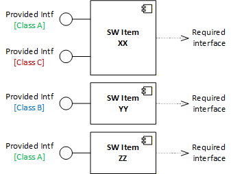
Example here uses sequence diagram showing the behavioral relationship and a component diagram showing the interfaces provided by each SW Item.
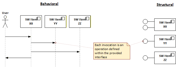
The process will involve “marking” the interfaces as we assess each hazardous sequence on the design.
Start off by marking all interfaces with safety classification of A (lowest) as shown below.
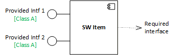
This will serve as foundation and we will increase the classification as we assess each hazardous sequence in Step 3.
Step 3) Assess each design and apply the safety classification to interfaces
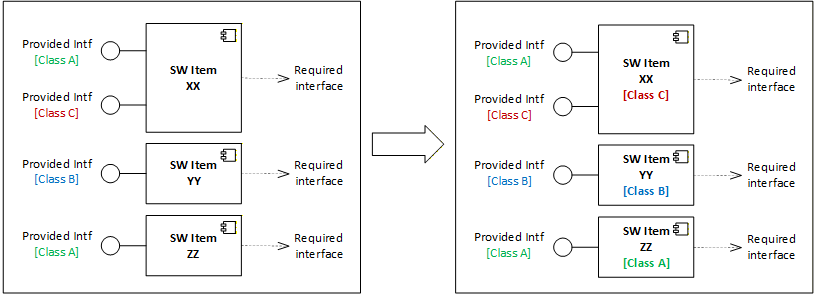
Assess each behavioral diagram and identify the invocations that are strictly contributing or related to the hazardous sequence. For each identified invocation, mark the interface with the safety classification of the related hazard risk, i.e., class A, B, or C.
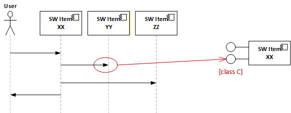
As we iterate through each risk item, overwrite with the higher safety class. E.g., if the item you’re working on is safety class C and there’s an existing safety class A on the interface, overwrite it with safety class C.
Once this activity is conducted for all hazard risks, we should end up with a safety class marking on all applicable interfaces as illustrated below.
I would like to point out that we’re assigning the safety class on the interface rather than the software item itself. This is to provide the architectural flexibility in composing the system.
The granularity classification can be on the interface or on the operation. This is for the team to decide based on how architecture/design is conducted.
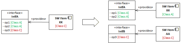
For example, if we want to split or combine a software item for risk segregation purposes, it’s a lot easier to have the safety class retained on the interface for composability purpose.
Step 4) Apply the highest safety classification to the SW Item
Apply the highest safety classification on the interface to the software item that is providing the interface.
We now have safety classifications on each software item and able to create a breakdown structure as illustrated below.
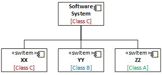
Steps 1-4 are recursive and can be applied to lower-level software item if the software system has multiple layers. The same method can be used for FMEA when hazard contributing scenarios are identified and new risks are generated.
Closing thoughts
Software risk segregation is not an activity the software team can “just do” at the end of development. It relies on existing software architecture/design that is built up over the course of project execution. It is an iterative process as risks are identified and mitigated.
Risk segregation is all about architectural justification. It is not about writing one or two bullshit sentences to justify why it’s a certain safety class. Just remember that risk segregation is ultimately for ensuring patient safety and also the auditor will not be interested in a “handwaving” verbal explanation.
Per IEC 62304, safety classification is tied to the required deliverables and activities (e.g., class A does not require design or unit verification deliverables). Because of this, you will see organizations being biased and lean more towards making the software items Class A. This is downright dangerous, lazy and unprofessional. My advice is just fucking do it properly and stop playing with patient safety. If you don’t know how to do it, then find somebody who can, and get out of the way.
Risk segregation requires a mature organization and people who understands software architecture/design (the proper way). If nobody in your organization knows what they’re talking about, it may be a safer bet to just set everything to safety class C and verify the shit out of everything.
Don’t waste time half-ass justifying how you lowered the safety classification with some bullshit rationale.
Leave a Reply